Complex Harness Design With Layup Board
One of the key design tools that we use at NSTG Engineering is HanWare, by utilising HarnWare we’re able to create highly actuated 2D cable harness drawings that include a full bill of material, schematics, cable cross-sections and much more.
But one area that we have not yet showcased is the ability to create 1:1 scale drawings that can be used to create layup boards for complex cable harnesses. We will now take you through all of the features we can include from the not-to-scale drawing all the way up to the 1:1 scale drawing.
Some of the images within this article may make it a little hard to see the detail, but we will provide a link at the end so you can view the PDF output.
The Not To Scale Harness And Outputs

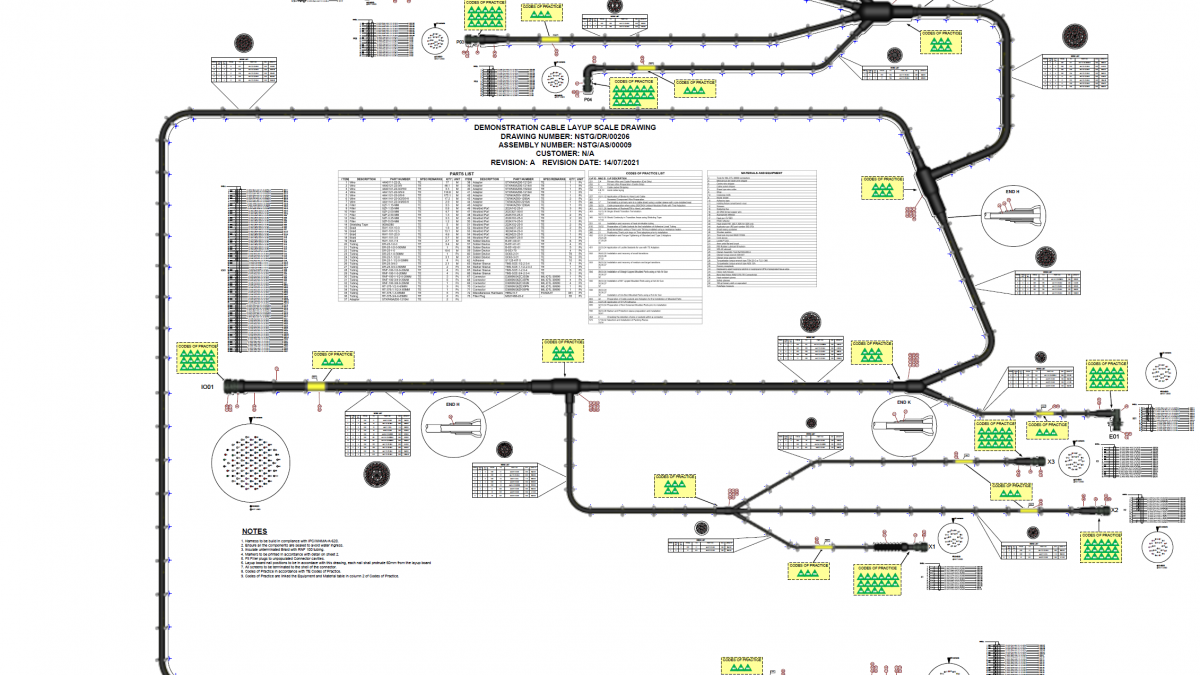
To start with we create a 2D drawing of the harness that is in a logical layout, the final layup board layout is finalised later. This 2D drawing contains detailed and accurate part stencils for all the key components in a cable harness, along with any notes or any applicable instructions.
This drawing also shows the overall dimensions of the harness as well as the dimensions of parts on the harness like maker sleeves.
Part balloons are also shown for each individual part in the harness.
At NSTG Engineering we always aim to keep all of the drawing information on one sheet, but in some cases like this one, it is not possible to contain all of the design information, this is one of those occasions.
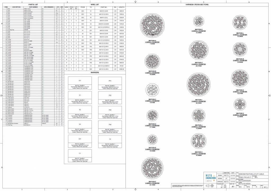
As part of creating the 2D harness, there are a number of key outputs that can be produced, which include the BOM, wire list, cross-sections and marker sleeve details.
The BOM contains all the parts that are required to assemble the harness, with accurate lengths and part counts for each part, as this will include a layup board the nails with the quantity required are also included in the BOM.
The wire list output provides an overview of the wires that are contained in the harness with the to/from detail, quantity, part number, diameter and length.
The cable cross-sections provide a detailed view of the construction of each harness leg, in this particular drawing, the wire list number is shown on each part to allow the harness builder to quickly look up the part(s) required.
A marker sleeve output is provided to show the parts that are required, font, font sizes, and colour of the marker sleeve, a separate output can also be produced so this information can be imported into a marker sleeve printer.
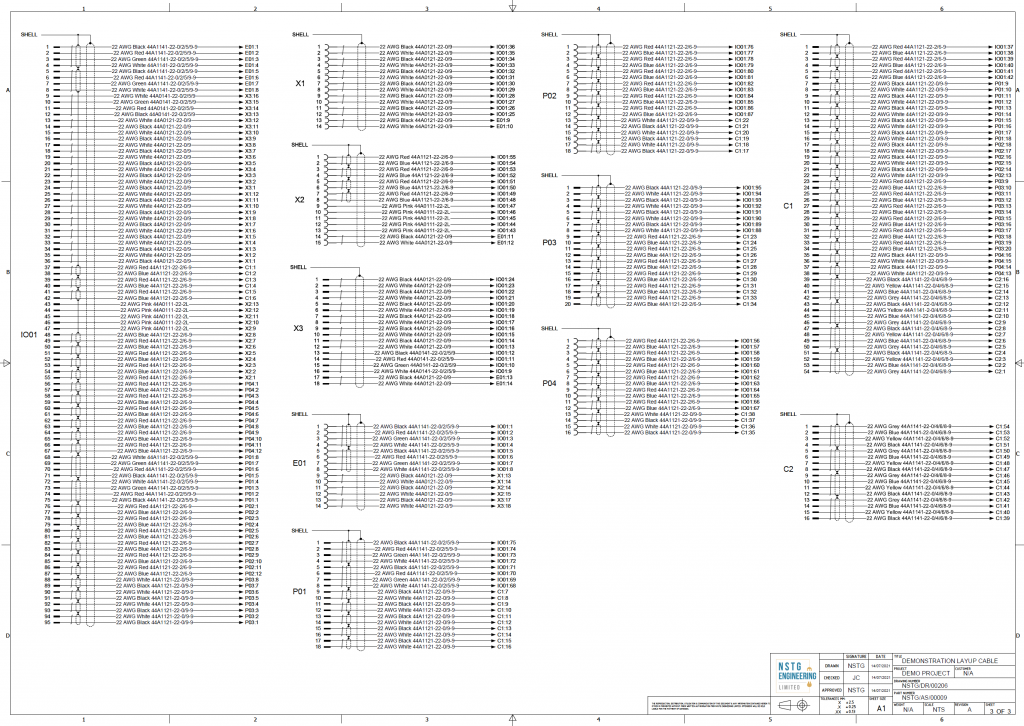
The final sheet includes the detailed schematic for the entire harness, as this is a complex harness design the schematic has been split out to show the connection of each connector. This drawing also shows the wire part numbers and gauge for each connection as well as show how the screens are terminated.
The Layup Board 1:1 Scale Drawing
Now, this is the part where HarnWare can really show off what it can do.
By utilising a separate tool called HarnVis we are able to create a full-sized harness drawing, firstly we add in the attributes that will create bends in the harness to allow it to fit within a layup board. Once this is done we are able to create a 3D harness and add in the layup board and pins.

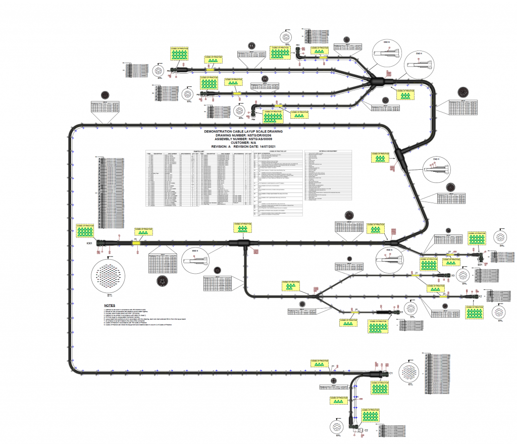
Now that the harness is fully defined in 3D we are then able to use this data to create a full 1:1 scale drawing of the cable harness.
This output will place the components accurately with the correct sizes along with the position of the pins that will be used to route the harness and keep components in place.
But layup boards rarely just have the outline of the harness and pins, there is usually a large amount of data to ensure the builder is not having to reference multiple drawing sheets when building the harness.
So to ensure ease of build we are able to gather all of the information from the main drawing pack and apply them to the layup board so all the relevant information is clearly displayed to the builder.
The detail provided includes:
- Wire list with cross-section diagram
- BOM with part balloons
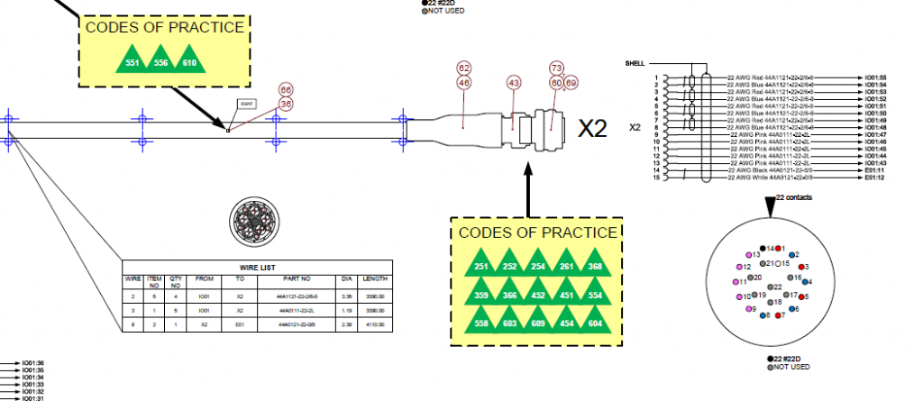
- Connector planform with wire colours on each contact as well as identifying unused contacts
- Schematic for each connector
- Cross-section diagrams for moulded part packing construction
- Codes of Practice with a lookup table to link each to the equipment or matierial required for the opperation
- Ident positioning
- Relevant notes and instructions
Further detail can also be added depending on the operating instructions required by the manufacturer.
At NSTG Engineering we are able to offer a full end-to-end service when it comes to designing cable harnesses and also provide an exceptional level of detail.
If you would like to find out more about how NSTG Engineering can assist with your next project, please get in touch, or if you would like to see our demonstrator drawing in all its detail you can download the PDF via the link below


